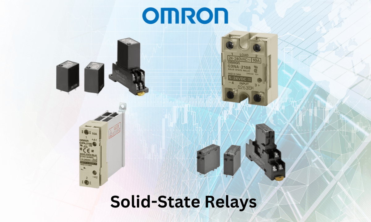
Solid-State Relays
Omron offers Solid-state Relays for diverse applications, utilizing semiconductor technology to enable high-speed and high-frequency operation.
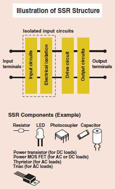
What is a Solid State Relay?
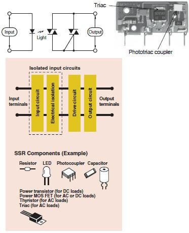
A Solid State Relay (SSR) lacks moving contacts but operates similarly to mechanical relays. SSRs use semiconductor switching components, including thyristors, triacs, diodes, and transistors.
Structure and Operating Principle
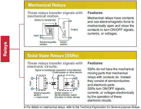
SSRs use electronic circuits to transfer a signal.
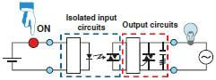
- When the input device (switch) is turned ON,
- Current flows through the input circuits, activating the photocoupler, and transferring an electric signal to the trigger circuit in the output circuits.
- This action causes the switching element in the output circuit to turn ON.
4. As the switching element turns ON, load current flows, illuminating the lamp.

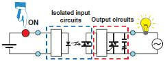
- Turning OFF the input device (switch),
- Deactivates the photocoupler, causing the trigger circuit in the output circuits to turn OFF, subsequently switching OFF the switching element.
- Consequently, the lamp turns OFF as the switching element deactivates.
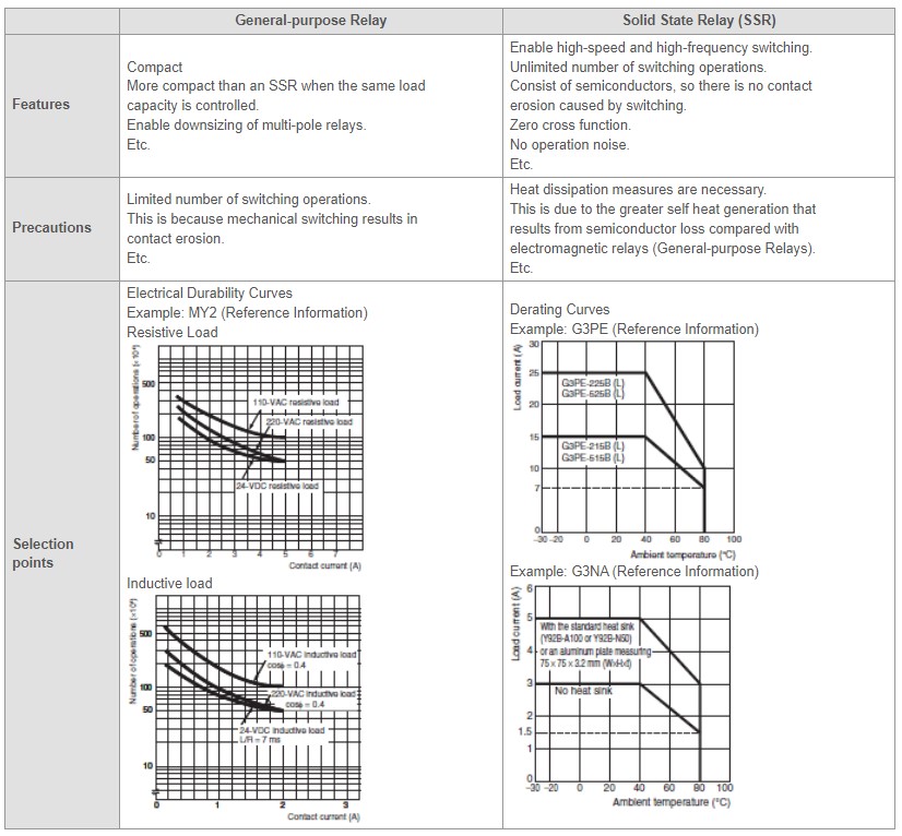
Features
SSRs employ semiconductor switches and optical photocouplers to isolate input and output signals. Photocouplers convert electric signals into optical ones, ensuring complete isolation while transmitting signals swiftly. Unlike mechanical relays, SSRs lack mechanical contacts, offering various unique features. Their standout advantage is the absence of wearing-out switching contacts.
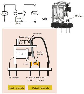
Mechanical Relays (General-purpose Relays)
In the case of an Electromagnetic Relay (EMR), applying input voltage to the coil generates electromagnetic force, which then shifts the armature. Subsequently, the armature synchronously toggles the contacts.
Solid State Relays (SSRs)
Representative Example of Switching for AC Loads
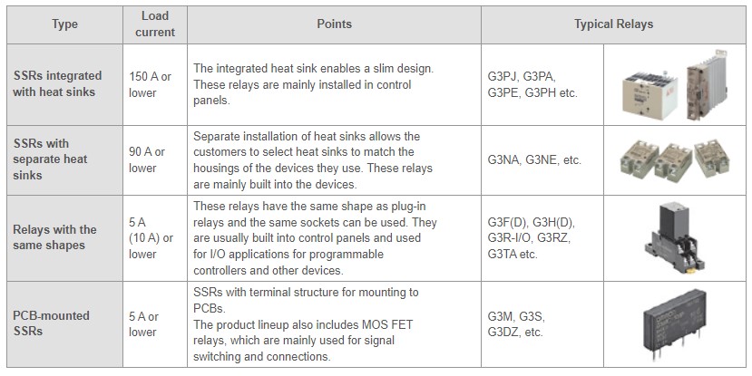
Types of SSRs
Omron classifies the SSRs according to type, as shown in the following table
Control Methods
ON/OFF Control
ON/OFF control involves toggling a heater using an SSR or electromagnetic relay based on voltage signals from a temperature controller. While an electromagnetic relay can perform this control, an SSR becomes essential when the heater needs frequent ON/OFF cycles lasting several years.
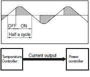
Phase Control (Single Phase)
Phase control adjusts the output based on current signals (4-20 mA) from a temperature controller, altering it every half-cycle. This method allows for precise temperature control and finds extensive use in semiconductor equipment.
Optimum Cycle Control
Optimum cycle control relies on the basic principle of zero-cross control, determining ON/OFF status every half-cycle for precise output timing.
While the accuracy matches conventional zero-cross control, optimum cycle control enhances precision by determining ON/OFF status each cycle instead of maintaining continuous ON output.

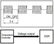
Cycle Control
Cycle control, specifically with the G32A-EA, involves toggling output voltage at a consistent 0.2s interval. This control method responds to current signals from a temperature controller within the 4 to 20 mA range.

Precautions for Cycle Control
When implementing cycle control, several precautions are necessary. Due to the rapid 0.2-second control cycle, there’s a substantial inrush current occurring five times per second. For transformer loads, this can lead to significant issues, such as:
- The SSR may risk damage if it lacks adequate rating margin.
- The breaker on the load circuit might trip due to the high inrush current, potentially making primary-side power control at the transformer unfeasible.
Interested to find out more about Omron Solid-State relay? Feel free to contact us!