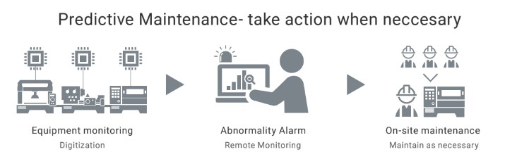
Predictive maintenance is the key to reducing unplanned downtime and operational costs
In response to significant shifts in business conditions, there’s a pressing need to transform the workplace. This entails reducing reliance on skilled maintenance personnel and embracing cutting-edge technology as the primary solution. However, surmounting cost and technological barriers can pose challenges. Omron addresses this by continuously monitoring and analyzing real data through frequent checks.
Remote monitoring of critical equipment using condition monitoring devices
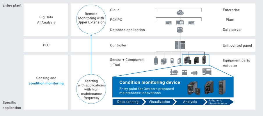
Resolve issues through condition monitoring
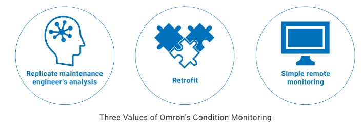
Our predictive maintenance solution replicates skilled maintenance engineer analysis, retrofits existing equipment, and enables remote monitoring. This technology simplifies equipment analysis, translating measurement data into alarms, facilitating quicker issue responses by maintenance engineers.
Improving existing equipment by implementing predictive maintenance
Production facilities and equipment, initially optimized by manufacturers, pose challenges when incorporating new functions. Extensive renovations and high costs deter such modifications, especially for critical, always-available production lines. Consequently, our condition monitoring device facilitates retrofitting, streamlining the addition of new functions to existing equipment.
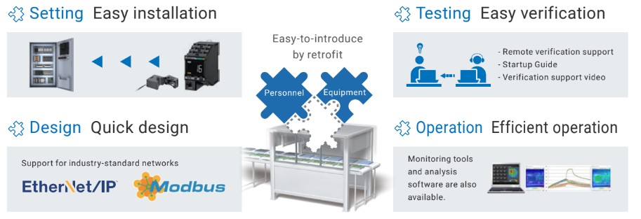
It minimizes labor and simplifies installation, verification, design, and operation for maintenance personnel. This design aligns closely with their vital maintenance responsibilities.
Accurate condition analysis
OMRON’s solutions apply their extensive know-how, including noise differentiation and tactile sensing for facility anomalies. They utilize the five senses-based maintenance techniques and tailor the ideal sensing method for each application, creating condition monitoring devices
Simple remote monitoring system
Specialized tools enable easy data visualization, facilitating assessment by anyone. Predictive maintenance at 1 meter above ground level can be seamlessly extended to higher levels, simplifying the introduction of remote monitoring without complex system design.
Specifications and Features of the Retrofittable Condition Monitoring Device:
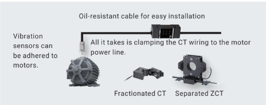
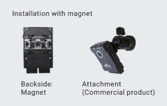
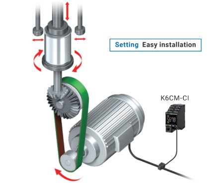
IoT sensors can be easily installed into existing equipment
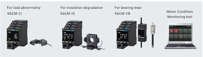
With motor condition monitoring devices:
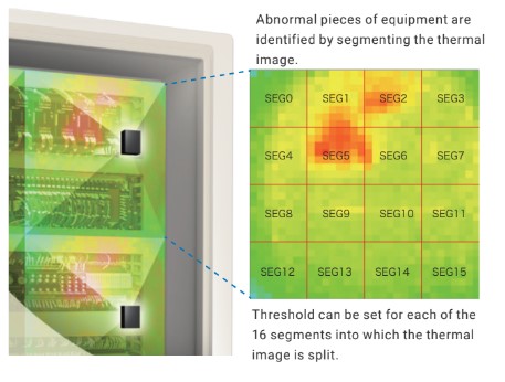
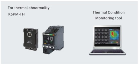
With thermal condition monitoring devices:
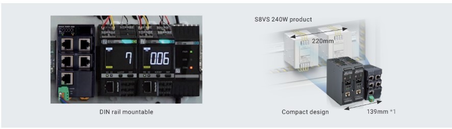
Compact design built for control panels
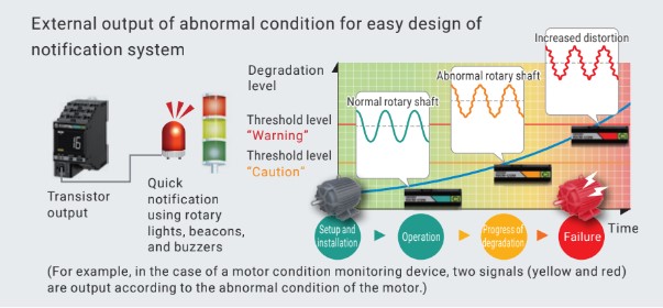
Alarm outputs available for on-site alerts
Simple design with transistor output
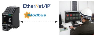
Equipped with industry-standard communications
Optional input voltage specifications can be selected depending on the installation location environment
You can choose the input voltage specifications for the condition monitoring device based on your installation environment. Options include AC 100-240 V type or AC/DC 24 V type.
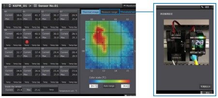
Simple operation with a dedicated monitoring tool
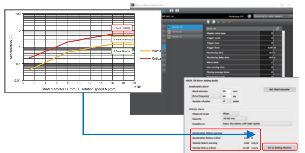
The monitoring tool visually represents facility conditions and automatically adjusts thresholds based on equipment, streamlining testing and implementation processes.
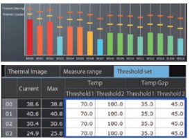
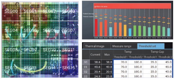
Quickly know the measurement analysis results in one view
Reduction of man-hours through automatic threshold setting according to measurement environment
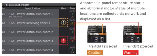
Remote visualization of in-panel temperature status and motor status of multiple locations
Detailed data, such as trend of measured values, can be confirmed remotely.
Easy to scale up as the number of measurement points increases
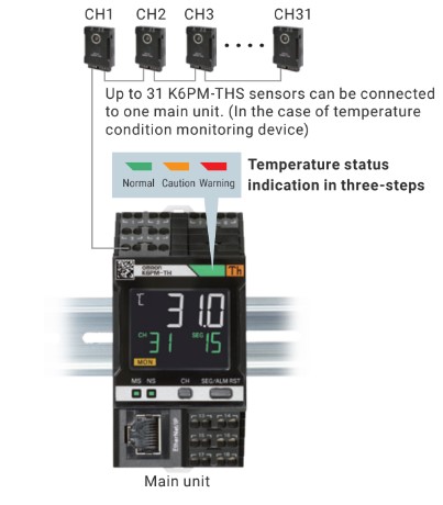
LCD displays allow on-site verification
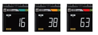
The status can also be checked on site from indicators (numeric/LED color).
Alarms notify abnormal condition
Displays the error condition with a value and color according to the set threshold.
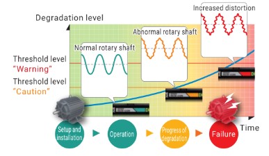
Increasing motor life in a filling facility by using the K6CM motor condition monitoring device
K6CM motor condition monitoring device
Effect: Prevent production problems by grasping the level of motor degradation
Detecting motor problems with a vibration gauge was unsuccessful, necessitating regular maintenance. The introduction of K6CM‘s current diagnosis enables precise issue identification through the “Degradation level” parameter. Continuous monitoring supports efficient maintenance aligned with motor deterioration. In contrast to vibration meters requiring motor modifications, K6CM‘s current diagnosis merely involves inserting CT between motor power lines, streamlining its application across equipment and expediting predictive maintenance.
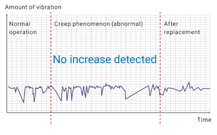
From: Limited motor monitoring with vibration meter
While the initial concept was to use a wireless vibration meter for monitoring, it necessitates periodic maintenance as it cannot identify motor abnormalities.
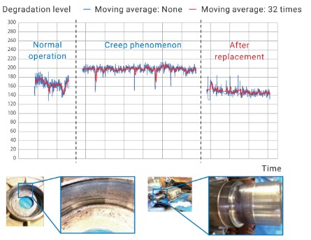
To: Using current analysis to determine motor abnormalities
Current monitoring enables the visualization of the level of degradation to determine the timing of maintenance.
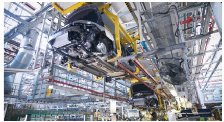
Remote condition monitoring of lifting station motor
K6CM motor condition monitoring device
Effect: Simple construction and introduction of a remote motor condition monitoring system significantly improve the efficiency of maintenance work
The lifter transporting workpieces to welding is crucial; any halt disrupts subsequent processes. Previously, personnel prioritized daily maintenance over data analysis and addressed issues reactively. K6CM’s introduction shifts data analysis to condition monitoring equipment, reduces system design time, as it retrofits onto existing equipment, and facilitates remote predictive maintenance implementation.
From: Corrective Maintenance
Constructing large systems and analyzing extensive data posed a significant time hurdle for adopting predictive maintenance, keeping corrective maintenance prevalent.
To: Easy system construction and simple data analysis enable the introduction of predictive maintenance
It’s easily retrofittable to existing equipment and supports industry-standard communication, enabling the implementation of a permanent remote monitoring system. Furthermore, the condition monitoring device performs data analysis, relieving maintenance personnel and promoting predictive maintenance.
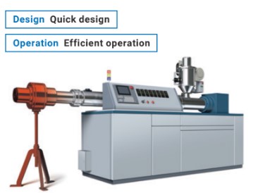
Remote thermal condition monitoring on extruder control panel
K6PM-TH thermal condition monitoring device
Effect: Improve maintenance efficiency through automatic threshold setting of the constant monitoring system introduced with reduced man-hours
Extrusion molding yields diverse products, necessitating varied in-panel device configurations and heat conditions. Temperature checks with thermo-viewers were prompted by a prior machine halt due to loose panel screws. However, determining normal/abnormal temperatures was subjective, relying on maintenance personnel’s experience. Automating this process proved challenging, as it required extensive man-hours to set temperature thresholds for each machine. K6PM-TH simplifies the process by automatically calculating optimal values for each machine and in-panel device configuration, enabling standardized judgments without relying on personnel intuition. This enhances system design and efficiency while constant monitoring accelerates anomaly detection, reducing facility shutdown risks.
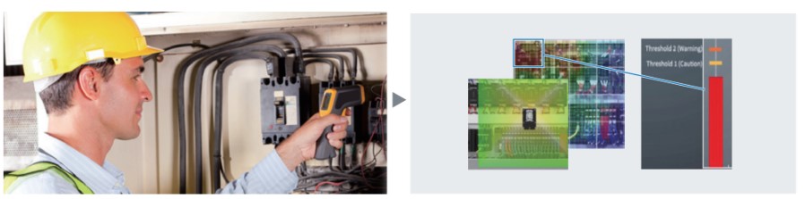
From: Manual thermal inspections
In high-load machines, temperature and temperature rise during normal operation vary with in-panel devices. Due to time constraints, inspections were limited to specific measurement points, relying on maintenance personnel’s experience and intuition, increasing the risk of missing abnormal heat signs.
To: Remote thermal condition monitoring
A wide-angle area temperature sensor constantly monitors multiple in-panel devices for abnormal heat generation. OMRON’s algorithm automatically sets alarm thresholds based on each device’s temperature, simplifying complex temperature monitoring without operator expertise.
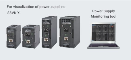
Preventing the stoppage of production facilities for manufacturing automotive parts with S8VK-X power supply
S8VK-X IoT power supply
Effect: Monitoring the power supply status to facilitate improvement and maintenance planning
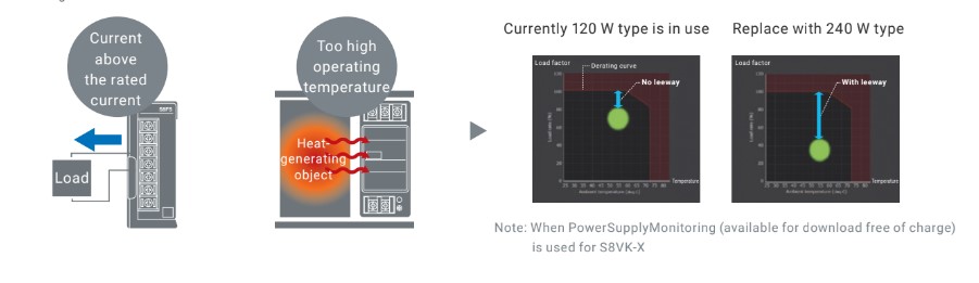
The longevity of power supplies can lead to issues like equipment failures. The company used OMRON’s S8VS series, aiming to replace power supplies proactively. However, there were cases where on-site checks displayed 0 years remaining, leading to rushed replacements. Sometimes, higher-than-expected current flow or elevated temperatures accelerated aging. The S8VK-X power supply allows continuous monitoring of voltage, current, peak current, and replacement time through communication, eliminating the need for on-site checks. It’s compact and fits in the original space during replacement.
From: Limited Visibility of power supply load conditions
The current fluctuates with machine operation. Despite normal operator checks, it can be high at times. In summer, monitoring power supply areas with CT or thermocouples is time-consuming.
To: Remote condition monitoring of power supply loads
Replacing the power supply with S8VK-X enables data checking and periodic data collection via communication, simplifying IoT system development and enhancement planning.
Customer Feedback
Retrofit Technology
This section introduces OMRON’s technologies developed to enable the introduction of “predictive maintenance” by retrofitting, without major system changes or modifications to existing facilities.
Current analysis in motors with inverters
Eliminate the noise effect that occurs periodically to detect motor abnormalities with high accuracy
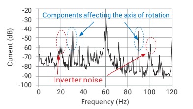
In inverter-driven or noisy environments, detecting motor issues using current elements is challenging, and retrofitting existing equipment faces obstacles. Therefore, we developed a technology to isolate abnormal motor components while filtering out noise, facilitating retrofits in noisy settings. Since identifying abnormalities amidst unknown noise in monitored current values or waveforms is complex, we perform frequency analysis. This analysis transforms the current waveform, making noise components evident. By pinpointing these noise components, we can detect motor failures in inverter-driven or noisy environments.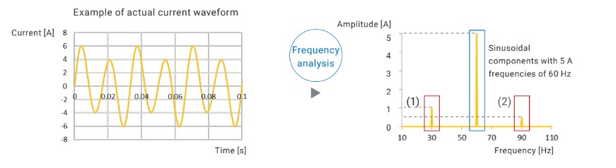
Degradation level detection algorithm
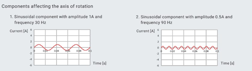
The motor’s current waveform undergoes frequency analysis to quantify abnormal frequency components relative to the motor drive frequency, detecting issues through “Degradation level 2.” By isolating rotation-affecting elements and filtering out inverter noise, stable measurements are achievable under inverter control.
Greatly reduce setup time with built-in auto threshold feature
Introducing automatic calculation of optimum alarm threshold according to the condition of the panel and ambient temperature to existing facilities
Determining optimal temperature thresholds for in-panel device monitoring can be challenging due to varying conditions. K6PM-TH simplifies this with a wide-angle lens, automatically setting thresholds based on an algorithm learning normal equipment temperatures. This reduces labor and standardizes threshold determination, enhancing maintenance efficiency. OMRON’s technology allows easy integration into existing equipment for a temperature monitoring system.
Auto threshold setting algorithm
The in-panel temperature profile varies with equipment and components, and inexperienced maintenance personnel may struggle with threshold settings. K6PM-TH, using historical temperature data from normal operation, automatically calculates optimal thresholds for each component, preventing temperature from reaching the ignition risk level.
Maintenance Tips
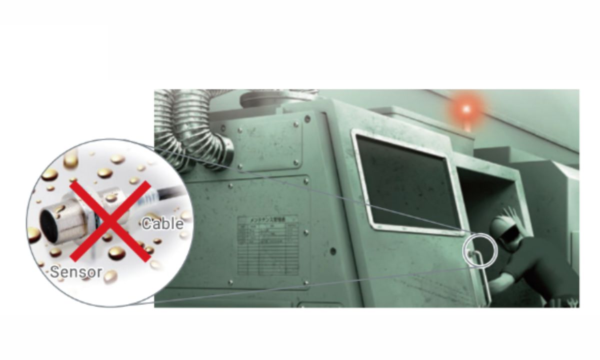
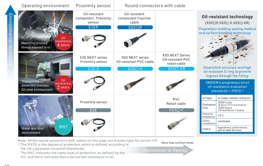
Round connectors and cables
Issue: The sensor inside the machine that injects cutting oil (coolant) is malfunctioning frequently, causing the facility operation rate to decrease.
Cause: Cable or round connector may be damaged from cutting oil.
In harsh environments with cutting oil exposure, sensor malfunctions can be caused by cables or connectors. Even if their appearance remains unchanged, cutting oil ingress over time reduces insulation resistance. This can lead to unintended short circuits and sensor malfunction. Detecting these issues during periodic inspections is challenging, often only noticed when a significant facility problem arises. Hence, it’s essential to make cables and connectors oil-proof to prevent such problems.
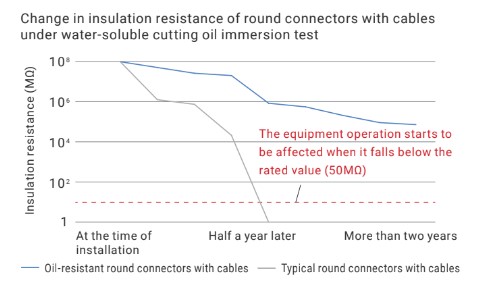
Fixing up: Replace with oil-resistant, round connectors with cables
that are resistant to cutting oil to reduce the risk of failure.
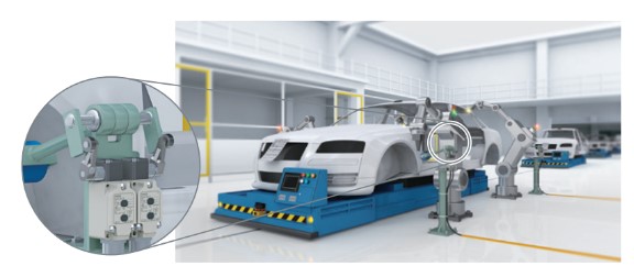
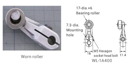
Limit Switch
Issue: Workplace detection at the limit switch is not stable
Cause: Incorrect actuator adjustments
Insufficient actuator adjustment during limit switch mounting can cause detection issues due to misalignment or switch wear. Exceeding the actuator’s rotation limit will damage it. Exercise caution.
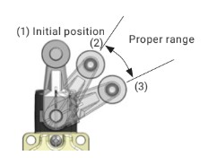
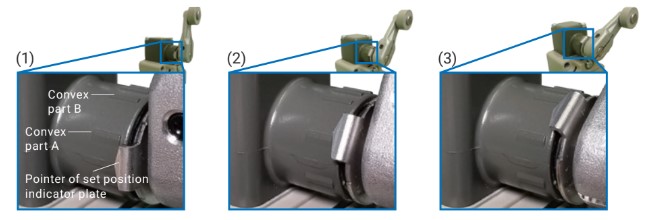
Solution: Adjust the position of the lever to detect the workpiece within proper pushing range.
Utilize the set position indicator plate on-site to position the lever correctly. After operation, adjust the indicator pointer to align it between the convex part A and convex part B of the bearing section for the correct pushing amount.
In applications with frequent limit switch use or when rotating rollers constantly contact moving objects, wear occurs in the roller’s inner diameter and shaft, altering the pushing action. In extreme cases, the roller may disengage. Actuators are available for individual purchase, and it’s advisable to inspect and replace them as needed during maintenance. Additionally, a range of durable levers with bearing rollers (WL-1A400) is offered as an alternative option.
Omron’s predictive Maintenance Solutions
IoT Power Supply S8VK-X
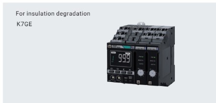
Insulation resistance monitoring device K7GE